DESCRIPTION
Objectives
The main objectives of the project are the realization of a simple theoretical and experimental technique for “natural” compressed sensing of data and a complementary one (also simple) for decompressed playback of data.
Project Description
The input image is encrypted and compacted in the Fourier (focal) plane of the lens where it can be recorded by a sensor. We exploit this ability to build a simple and inexpensive – albeit less efficient – compressed sensing instrument. The Fourier transform, just like the Hadamard transform, encrypts and converts redundancy in sparsity but less efficiently. The properties of the Fourier transform are known quite well and, in many cases, we know a priori the place in the Fourier spectrum where the most energetic diffraction orders are sent. Usually, this is the centre, the intersection of the Fourier plane with the system axis, but there are energetic orders also in the direction of maximum regular variation of the object image. Therefore, we know a priori in many situations where to sample the Fourier spectrum to acquire most of the information needed to reconstitute the original image.
We compensate for the weaker encryption power of our technique by adding encryption elements and keys as those used in optical processing of information techniques or mathematical encryption using permutation of the rows and columns of the output data matrix according to a key. The receiver needs for decryption purposes, besides the compacted data, all the keys, which may be transmitted separately. Also, we complement the above technique with a reciprocal, a “natural” decompressed playback tool using an SLM and optical processing of information arrangement. The encrypted image for this system will be computed numerically using the iterative Fourier transform algorithm IFTA for the creation of diffractive optical elements (DOE) [5,6,7]. The compactization is realized by forcing the amplitude to take an a priori form compact form and the encryption by forcing the phase distribution to have an a priori additive factor. The decryption key is inserted as the conjugate (the negative of the) phase additive factor by the computer program in control of the SLM phase distribution. The decryption and decompression procedures are performed by an optical lens processing of the information system.
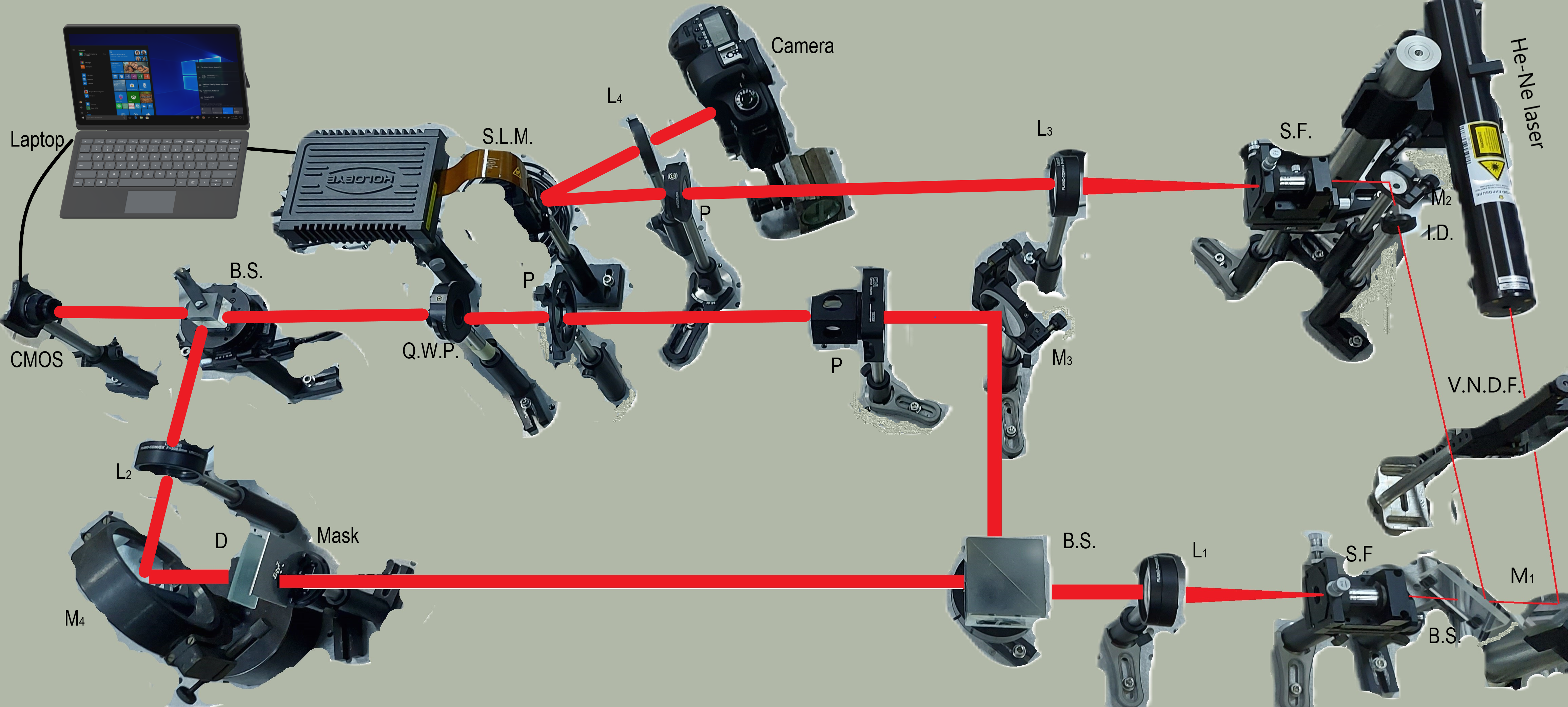
Fig. 1 Experimental setup for encryption - compaction and decryption - decompression.
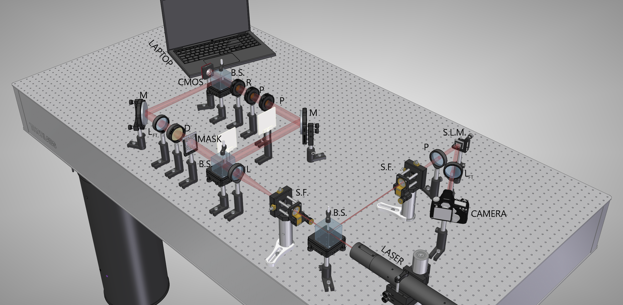
Fig. 2 CAD design of the encryption (left side) and decryption (right side) setup
The realization of our proposal is made by the development of the digital phase-shift holography technique which permits multiple holographic recordings in which the phase retardation in one arm of the interferometer is changed, a technique related to phase-shift interferometry. Out of these recordings, one can extract both the amplitude and phase information of the electromagnetic field in the sampling plane. This solves an additional difficulty brought by the use of the Fourier transform instead of the Hadamard transform, namely the fact that the phase information is relevant. This is the main difference between photography and holography. Phase-shift holography has already been used for encrypting purposes but in the optical processing of information sense, not in the compressed sensing sense we proposed.
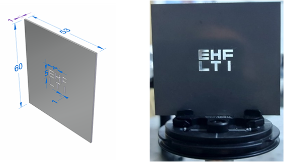
Fig. 3 Binary mask used as an object, for encryption and decryption.
To obtain the image of the mask we used the following steps: recorded the object information, created and applied the key (hologram) of encryption/decryption in Mathematica, calculated the Fourier transform and key (hologram) rendering on the SLM (Spatial Light Modulator).

Fig. 4 Hologram used for the recorded image rendering.
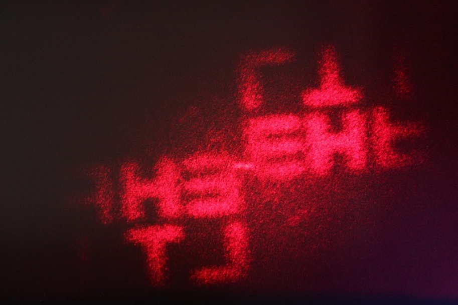
Fig. 5 Picture, taken with a photo camera, of the mask projected by SLM (final image).
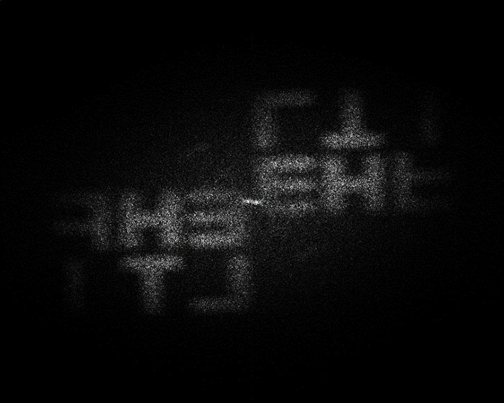
Fig. 6 Image of the mask, recorded with the CMOS camera (initial image).
To be projected with the spatial light modulator, the image's resolution from Fig. 6 was modified through a recurrence algorithm created in Mathematica and transformed into holograms (Fig.4).
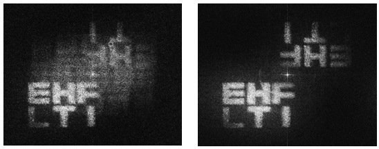
Fig. 7 The reverse Fourier transform of the hologram.
In the left picture (Fig.7) is the reverse Fourier transform of the hologram (Fig.4), and in the right is the reverse Fourier transform of the bleached hologram. We tested if the Fourier transform F2=fft(F) was correctly calculated. And it was because we obtained the original/initial entry. We used the iterative Fourier transform algorithm (IFTA) for digital bleaching.
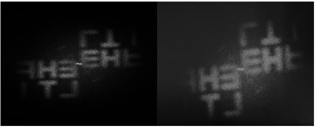
Fig. 8 The mask images (left - image recorded on CMOS camera used for decryption, right - image recorded on photo camera (Fig.5) in grey level).
Besides the experimental setup, we have created and used programs/algorithms like an encryption-decryption key; recurrence; measured (compared) the intensities of the object and reference images and the iterative Fourier transform for digital bleaching.